|
|||||||||
|
|||||||||
|


| Home|About Us|Products|News|About Ozone|Application|Contact | |
| Home > Products > Ozone AnalyzerOzone Analyzer |
LF-100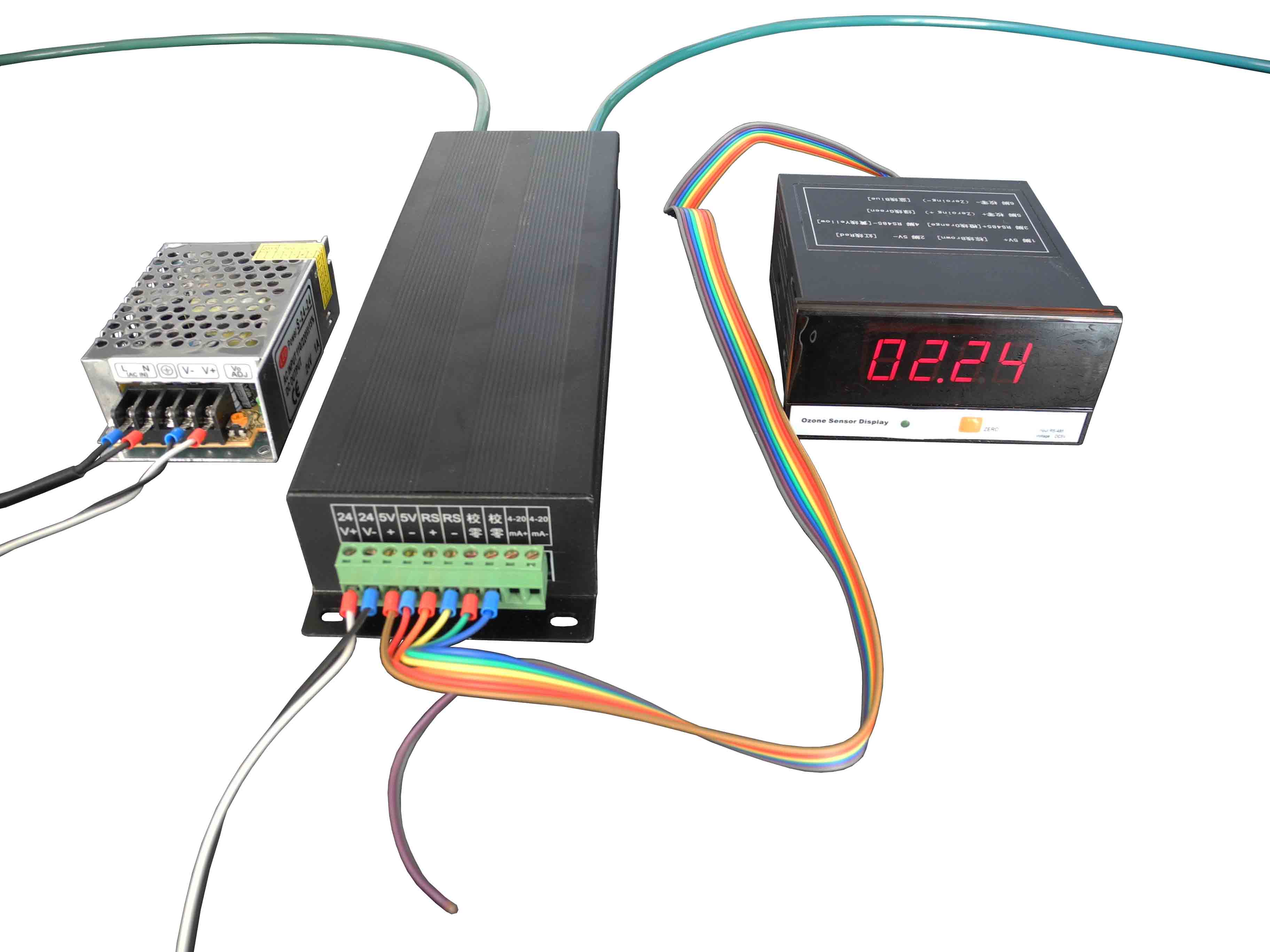
Principle: UV dual optical absorption method for real-time detection outlet concentration ozone generator.
Range: 0 ~ 200g/m3 (0 ~ 40 g/m3, 0 ~ 100 g/m3, 0 ~ 200 g/m3 optional fixed range);
Inside picture: 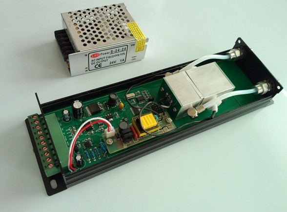
Model LF-100 mainly use for the ozone concentration of ozone generator outlet; Which adopt UV lamp as light source system; The working life is up to 30,000 hours or more; it works stability and with high precision as well;
The sensor adopts double cuvettes structure to absorb high pressure and high flow gas, and there is no leakage during the working.
It is easy to keep clean, easy for both maintenance and operation as well.
The model LF-100 must be effected “Zero calibration” by hand before working, which ensure the higher accuracy, and meanwhile to avoid zero drift happening during the working;
The ozone sensor is a high-tech product specific application of photoelectric detection technology. Which adopt the microprocessor advanced control technology and light-source long-life pulse mode, the characteristic of UV absorption for the ozone gas, designed based on the law of Bill Lambert (Beer-Lambert);
Technical parameters and installation
Detection principle: double cuvettes Range: 0 ~ 200 g/m3; (0 ~ 100g/m3, 0 ~ 40g/m3 optional). Display resolution: 0.01g/m3; Display digits: 4; Accuracy: ± 3%; Communication: RS-485; Communication parameters: 9600,8, N, 1; Output: Differential 4-20mA, linear; Weight: 0.8kg; Input gas flow: 1.0 ~ 2.0L/min; Input gas pressure: up to 1bar (0.1MPa); Power supply: DC 24V (standard adapter); Size: one type of 220mm (length) × 75mm (width) × 35mm (depth); 1 module Gas inlet, outlet pipe diameter 4mm, OD 6mm; 
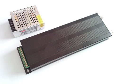
Product structure:
This paragraph ozone sensor and display by the host header of two parts, the structure as shown below: 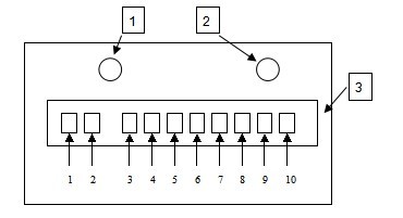
1. The inlet and outlet of the ozone gas; (inlet, outlet inner diameter 4mm, outside diameter 6mm.) 2. The inlet and outlet of the ozone gas; (inlet, outlet inner diameter 4mm,outside diameter 6mm.) 3. The Power and terminals for both signal input and the output;
The Power and terminals for both signal input and the output defined as follows: 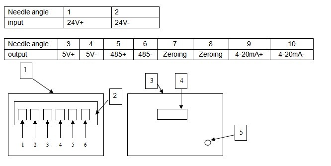
Ozone sensor display header
1.485 display header 2. Signal input terminals 3. Front panel 4. Display window 5. Zeroing button
The terminals of signal input defined as follows: 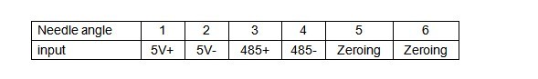
The ozone sensor starting working when turn on the switch. The warm- up time is 10 minute for the first time operation. Please connect with ozone after 10 minute for the first operation. Make sure to connect both the electrical and pipe correctly, adjusting the gas flow at1.0 liters/Min ;
The “zero calibration” of model LF-100 is manual zeroing. Pls start “Zero calibration after the warm -up time; To make sure the accuracy of “ Zero calibration” , please don’t connect with ozone gas during the warm- up time.
The UV sensor to use:
1. Connect electrical, piping, communication cable properly; 2. Warm-up time 10 minute. 3. Manual zero (just press the button on the front panel) 4. Measuring ozone concentration; 5. Data display, output, key operation processing and data communications; 6. Please carry on manual zero if the error is higher than 1%; close off ozone source when zero calibration; 7. Ensure that there a bus only to connect with computer when reading or writing RS-485 address, otherwise it will cause IP addresses conflict; 8. Make sure the ozone gas dry and clean. Need add air dryer and dust filter if necessary.
Note:
1. The gas dew point should be less than 5 ℃, or the gas must be dried. 2. UV sensor must operate under condensation environment; 3. To ensure the stable gas flow, adjust the ozone flow at 1.0L/min; 4. The ozone gas need be recycled or destroyed, and can’t leak into the indoor.
|